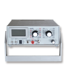
Surface point-to-point resistance tester
Main use:
The point-to-point resistance tester/fabric surface resistance tester is used to measure the point-to-point resistance of fabrics such as carpets, films, insulation materials, etc., to test the anti-static performance of textile test materials.
Testing standards:
GB120114-2009
Main features:
1. It mainly consists of two parts: a flat electrode device and a high resistance meter;
2. The resistance value is directly displayed by numbers, with high accuracy, fast display, good stability, and convenient reading;
3. Built in timer, automatically locks the reading after 15 seconds.
Technical parameters:
1. Adopting a highly integrated 31/2-digit digital display.
2. Range: 1 × 10⁵ Ω~1.999 × 10¹³ Ω
3. Test voltage is DC100V or customized
4. Working environment temperature: 20 ℃± 2 ℃, humidity: 35% ± 10% RH
5. Test accuracy: ± 5% when ≤ 1012 Ω; When>1012 Ω, it is 20%.
Detection steps:
1. The high-voltage output end and measurement input end of the instrument are respectively connected to two electrodes (the shielding end is not used). The conductive rubber is placed on the surface of the test sample at a certain distance according to the standard requirements, and the electrodes are placed on the conductive rubber.
2. Set the multiplier (range) switch to the low gear. The low magnification of this instrument is × 105 Ω, and resistance measurement must start from the low range. This is because the measured object may have a large distributed capacitance, which may cause charging current to harm the highly sensitive input terminal of the instrument at the moment of measurement.
3. Turn the high-voltage (zero calibration) selection switch to the "discharge zero calibration" position above 100V.
4. Turn on the power switch of the instrument.
5. Depending on the specific situation, turn on the Filter 1 or Filter 2 switch.
6. Zero calibration - Confirm that the high voltage (zero calibration) selection switch has been set to the "discharge zero calibration" position above 100V, adjust the zero calibration knob (8) to make the instrument reading. 000.
7. Turn on the timer switch.
8. The charging time required for a 100V test voltage is very short. Quickly turn the high voltage (zero calibration) selection switch to 100V, apply the test voltage to the tested object, start the resistance measurement, and start timing. After 15 seconds, the "H" character is displayed in the lower middle of the left side of the display screen, and the displayed value is automatically locked.
9. Record this value. Turn the switch to the "discharge calibration zero" position, at which point the measured voltage is disconnected and the discharge circuit is connected. After about 15 seconds, the tested device is fully discharged, and the operator can only contact the high voltage end and the measurement end.
10. After an interval of 3-5 minutes, move the electrode after the residual charge on the tested sample is fully released, repeat the above steps, and proceed to the next set of data measurement.
11. After completing all tests, turn off the power switch, turn off the timer switch, and turn off the filter 1 and filter 2 switches; Turn the high-voltage (zero calibration) selection switch to the "discharge zero calibration" position above 100V; Set the multiplier (range) switch to the low gear position; Organize and properly place the test sample holder, power cord, electrodes, and conductive rubber.
Notes:
1. Before starting the operation, the instrument power should be in the off position. After the previous measurement is completed, an internal discharge time of about 30 seconds should be passed to ensure that the operator is not subjected to high-voltage electric shock;
2. Built in battery and external power supply, only one power supply method can be selected;
3. Please place in a dry and ventilated place when not in use;
4. When not in use for a long time, please remove the battery from the battery box to avoid battery leakage and corrosion of the instrument;
5. Non professional maintenance personnel are not allowed to open the instrument cover to prevent electric shock caused by high voltage inside the machine. Opening the cover without authorization and disassembling or changing the internal components of the instrument may result in losing the instrument's warranty qualification or increasing repair costs.
6. It is strictly prohibited to use corrosive fluxes such as hydrochloric acid and solder paste to weld measuring wires, connectors, or internal components of instruments, in order to avoid irreparable leakage faults.
 WeChat platform on the scan
 Copyright:Qinsun Instruments Co., LTD! Qinsun Instruments Co., LTD!Provide technical support Enterprise email