INTRODUCTION
The plastic industry is to play a major role in automotive industry, which is on the brink of a revolution. The real plastics revolution in automotive industry began in 1950 when thermoplastics made their debut, starting with ABS and going on to polyamide, polyacetal and polycarbonate together with introduction of alloys and blends of various polymers. The ongoing development of advanced, high-performance polymers has dramatically increased their usage. Originally, plastics were specified because they offered good mechanical properties combined with excellent appearance, including the possibility of self-coloring. The application of plastic components in the automotive industry has been increasing over the last decades. Now a days, the plastics are used mainly to make cars more energy efficient by reducing weight, together with providing durability, corrosion resistance, toughness, design flexibility, resiliency and high performance at low cost.
Beardmore and Johnson (1986) emphasized the potential use of fiber-reinforced composites in automobiles from semi-structural or decorative parts to primary structural areas of the vehicle, such as, body structures.
The vision for the future of automobiles by 2020 in National Composites Network (2005) is that the automotive industry will establish plastics as a material of choice in the design of all major automotive components and systems, like, interior, body, exterior, power train, chassis and light weighting. To realize the vision, plastics producers and automakers will work to maximize the value of polymers throughout the supply chain and over the entire life cycle of the vehicle. Now a days, polymer composite is preferred material for enhancing component and system value, polymer based architectures are giving automakers the freedom to create innovative vehicles that increase the value throughout the supply chain and for the driving public, designing with composites positively impact vehicle cost, environmental performance, and customer preferences. We can realize that, polymer is the principal tool to produce safer, more affordable, stylish, durable, energy efficient, and low emission vehicles in every market segment. Rapid, cost-effective processing systems will provide automakers with the flexibility to respond to dynamic markets in future. Das (2001) concluded in his report to Department of Energy, U.S. that cost-effectiveness of mass-produced composite components can only be achieved by using low-cost, high-reliability materials, new high-speed processing techniques, and new structural design approaches that are tailored for fiber-reinforced polymer materials. DOE,in partnership with the USCAR’s Automotive Composites Consortium (ACC), is sponsoring research under the Lightweight Materials Program that seeks to overcome the barriers to more widespread use of composites in automotive applications.
Blau and Budinski (1999) focused on the Committee G-2’s work in developing new wear testing standards and illustrated how specific standards can be used to solve practical wear problems. The principal advantages of using ASTM standard wear test methods includes rigorously evaluated test method, carefully documented procedure, the repeatability and reproducibility of results,in many cases, a great deal of previous data exists and it is convenient to compare new results with the existing data and documentation and reporting requirements have been established so that all the major variables and results of the work can be presented in a complete and organized manner.
This project work developed a rubber wheel abrasion testing machine, as per schedule ASTM G65-04-2010, for estimation of three body abrasive wear of automobile components, which are varying from low to medium, medium to extreme abrasion resistance and thin coatings.
LITERATURE REVIEW
The abrasive wear was first described and used by Robin in 1910, in which a specimen, 15 mm dia., under a unit load of 1 kg/cm2 was rubbed against the surface of a cloth fixed to the flat surface of a disc revolving at 150 rpm. Friction took place 72.5 mm from the disc axis, and wear was determined over a friction path of 200 m. Lancaster (1969) reviewed the main features of the twobody and three-body abrasive wear of polymers and attempted to identify the various physical processes.
Khruschov (1974) reviewed the mechanism of abrasive wear and suggested the Kh4-B test machine, in which an abrasive cloth is fastened to the flat surface of a 250 mm disc which revolves round a vertical axis at up to 60 rpm.
The end of a cylindrical specimen (diameter 2.0 mm, length 15-20 mm, and clamped in a collet holder) rubs against the cloth under a stress of 0.3 kg (unit pressure 9.55 kg/cm2). The specimen moves radially 1 mm per revolution of the disc, so that a spiral friction path is made on the cloth. The surface of the cloth is divided into several zones of similar spiral length (the zones with odd numbers for test material and those with even numbers, for the standard material). The test specimens and the standard material of similar size are tested under similar conditions over a path of 15 m. This test method ensures good repeatability (variability 2-3%). Thorp (1982) used a tri-pin-on-disc rig to determine the friction, fatigue and abrasive wear properties of a number of commercial polymers like, Nylon, UHMWPE, PTFE, and Polyurethane based bearing materials against steel gauze and abrasive paper. Hutchings I.M. (1992) elaborated the theory,testing methods and experimental analysis of various types of wear while ASM (1992) emphasized on practical information to provide tribologist with the tools needed to understand the tribological behavior of materials and solve problems on the job. Stevenson Hutchings (1996) developed the dry sand/rubber wheel abrasion tester.
Budinski (1997) described the abrasion resistance ranking of 17 plastics and 4 elastomers by using modified, ASTM G-65, the dry-sand rubber wheel abrasion tester to identify a material that would provide longer service life. Trezona and Hutching (1999) employed the ball-cratering micro-scale abrasion apparatus to study the morphology, evolution of wear scar and behaviour of polymethylmethacrylate (PMMA).There are many authors, who used rubber wheel tester in their research work, viz., Cenna A. A. et al. (2000) and Harsha A.P. et al. (2003) used polymer composite, Chacon-Nava J.G. et al. (2010) investigated metal wear, Deuis R.L. et al. (1998) and Thakare M.R. et al. (2012) applied on coatings, Ravikumar B. N. et al. (2009) assessed abrasion resistance of reinforced PA66/PP nano-composites. The data obtained from tests on components of the system are widely used to predict wear in laboratory tests. Hutchings (1992) suggested various methods for testing of abrasive wear, like Pin on abrasive disc (ASTM G99-05-2010), pin on abrasive plate or drum (ASTM G132-96-2013), or rubber wheel abrasion test (ASTM G65-04-2010).
DEVELOPMENT OF ABRASIVE WEAR TESTER
The rubber wheel abrasion test is a most popular method for estimating the dry/wet three body abrasive wear of components. The working principal of rubber wheel abrasion tester is shown in figure 1. In this tester,the abrasive of known size and composition at controlled flow rate is introduced between the test specimen and rotating rubber wheel. The test specimen may be of any material or coated surface. The test specimen is pressed against the rotating wheel at a specified force by means of a lever arm. The rotation of wheel at constant speed in the direction of abrasive flow abrades the test surface.
The mass loss is then measured, using weighing machine, by subtracting the mass of specimen after test from the mass of specimen before test. Variation in density of abraded materials requires the abrasion measurement from loss in volume by using formula:
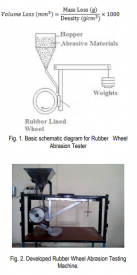
In the developed machine, as per ASTM G65-04(Reapproved 2010) schedule, the rubber wheel is rotated by means of a gearbox having ratio 7.75 and can transmit torque up to 38 Nm at 200±10 rpm, which is coupled to 3 phase, 1 hp, AC drive motor. The specimen holder is fixed on the vertical arm of lever to hold the specimen at diameteral line of rubber wheel, which hold the specimen of cross section 25mm X 75mm and varying thickness from 3mm to 12 mm. Depending on the material being tested, the load hangs on horizontal arm of lever. The lever is of cross section 30mm X 12 mm. A hopper is mounted on top to flow abrasive through nozzle between specimen and rubber wheel.
APPARATUS AND MATERIALS
Developed rubber wheel abrasion testing machine consists of several elements, which are of critical importance to ensure uniformity in test results among laboratories. These are the specified rotation of rubber wheel, sand nozzle to flow abrasive particles at required flow rate and lever arm system to apply the requisite force.
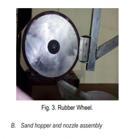
A. Rubber wheel:
It consists of a steel disc made of SS 316 grade with an outer layer of cured rubber molded to its periphery. The optimum hardness of cured rubber is in the range of Durometer A-60±2 measured as per standards guidelines. Rubber wheel is shown in figure 3.
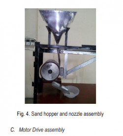
As shown in figure 4, the assembly is made up of SS 316 material to flow abrasive particles. The Narmada rounded quartz grain sand of maximum 0.5 weight percentage moisture content will be used. Hopper is designed to handle 15 kg of sand, which is sufficient to perform test. Nozzle fabricated as per dimension mention in standard, which is developing sand flow rate of 300 to 400 g/min.
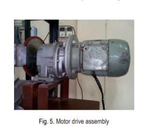
The rubber wheel is driven by means of a gearbox having ratio 7.75 and can transmit torque up to 38 N-m at 200±10 rpm, which is coupled to 3 phase, 1 hp, AC drive motor. The motor drive assembly is shown in figure 5.
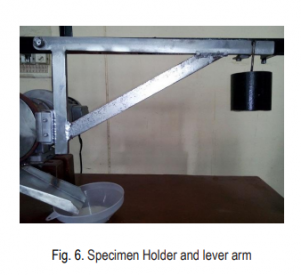
D. Specimen holder and Lever arm
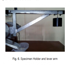
The specimen holder is attached to the lever arm of cross section 30mm X 12 mm., as shown in figure 6, is made by mild steel and pivoted in line with contact point of specimen of cross sectional area 25mm X 75mm and varying thickness from 3mm to 12 mm. An appropriate number of weights, as per requirement of procedure, are applied to apply the required force between the test specimens and the rubber wheel.
TEST PROCEDURE
The test procedure involves first step to clean specimen followed by weigh the specimen nearest to 0.001 to 0.0001 gm. Next step is to seat the specimen securely in the holder and add the weight to lever arm and set the revolution counter or stop watch, which depends on type of specimen materials. Maintain uniform curtain of sand by flowing sand at prescribed rate and then start the wheel rotation and lower the lever arm carefully to allow the specimen to contact along the horizontal diametral line of the wheel. After completion of test, lift the specimen away from the wheel and stop the sand flow and wheel rotation. Remove the specimen and reweigh to know the mass loss of specimen.
WEAR CALCULATION AND MODES OF WEAR
The wear rate is calculated by using Archard’s wear equation. Graphical results between various parameters, viz., load (N), sliding distance (m), wear volume removed (mm3), wear rate (Kg/N-m), wear coefficient k (mm3/N-m), dimensionless wear rate, etc. can be used to know the wear characteristic of tested materials. Modes of wear like, micro cutting, micro ploughing or fatigue failure can be found out by using scanning electon microscopy(SEM) and/or transmission electron microscopy (TEM) analyzer.
DISCUSSION
Developed testing machine is suitable for 3-phase,50 Hz, AC supply with gearbox to provide 200±10 rpm at load. Easily available Narmada sand as per recommended shape and moisture content of required grain size is used as an abrasive agent in place of costly Ottawa sand. The sand flow through specified fabricated nozzle at flow rate of 300 to 400 g/min. Overall low cost of machine, without compromising on standards, makes it attractive for abrasion test.
CONCLUSIONS
The developed rubber wheel abrasion testing machine will be used to estimate the abrasive wear of automobile components, which are varying from low to medium to extreme abrasion resistance and thin coatings by using procedure A, B, C, D or E as described in ASTM G65-04(Reapproved 2010) schedule, to achieve the main aim of this project work.
FUTURE WORK
This abrasion tester will be equipped with electronic components to read the variables viz., rpm counter, sand flow rate and applied force between the test specimens and the rubber wheel. Interfacing of these digital inputs will facilitate the digital and graphical output by using computer.
ACKNOWLEDGEMENT
The authors would like to acknowledge the management, workshop staff and students of Shri Vaishnav Polytechnic College, Indore for providing the facilities, support and assistance for the development of rubber wheel abrasion testing machine.
Prev: Wash Color Fastness Test Operating Steps
Next: Evaluation of friction force using a rubber wheel instrument
 WeChat platform on the scan
 Copyright:Qinsun Instruments Co., LTD! Qinsun Instruments Co., LTD!Provide technical support Enterprise email